Guide · Buyer essentials
Precision Shaft Design Checklist for Pump, Motor and Gearbox Shafts
What to specify on a shaft drawing: material, fits, runout, keyways, threads, finish and heat treatment.
ISO 9001:2015 Certified
Documented quality management system
Mitutoyo Quality Inspection
Calipers, micrometers, height gauge, DTIs
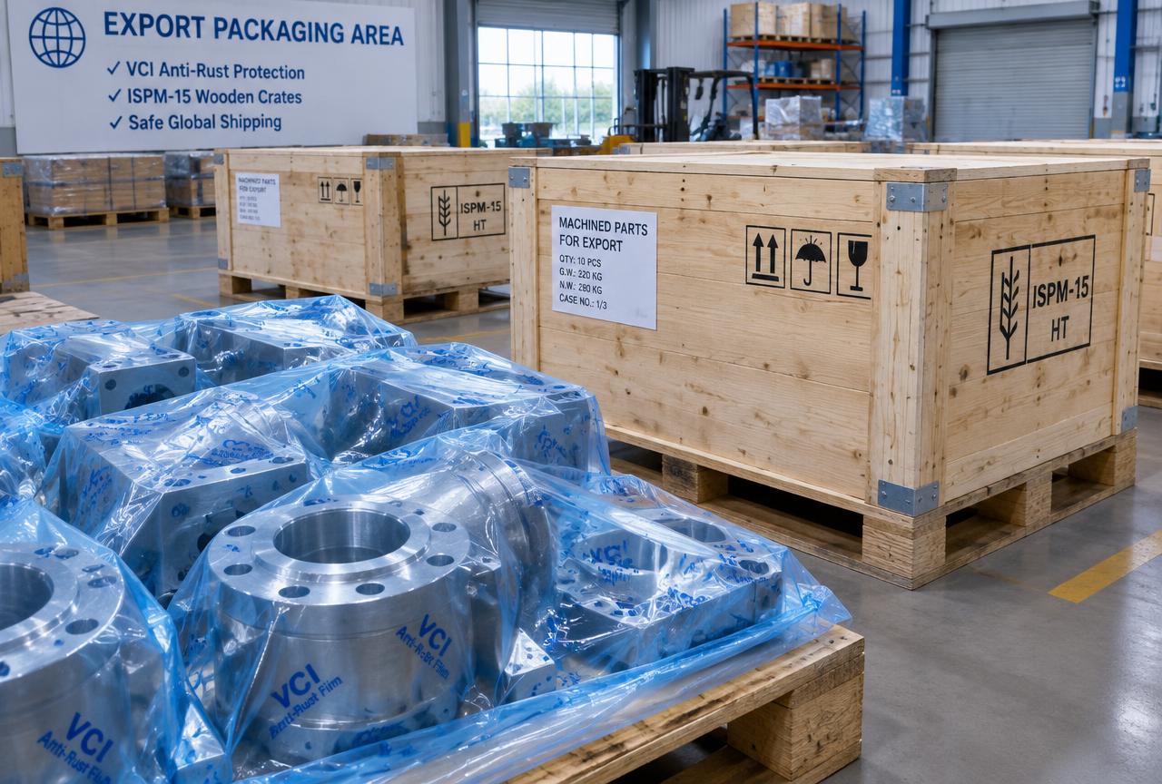
Export-Ready Packaging
VCI film, ISPM-15 wooden crates
RFQ Response in 24 Hours
Quote within one working day
NDA Available
Your drawings stay confidential
On this page10 sections
What a shaft drawing has to state
A pump, motor or gearbox shaft is cheap to quote and expensive to get wrong. Everything below is routinely missing from first-issue drawings.
Specify these
- Grade and condition together, for example SS 316 annealed, or EN24 hardened and tempered
- An EN 10204 3.1 material certificate where traceability matters, requested at RFQ stage not after dispatch
- ISO 286 fits on bearing seats and seal diameters: k6 or j6 on journals, h6 where a sliding fit is wanted
- ISO 2768-m as the general tolerance so non-functional lengths and diameters are priced sensibly
- Runout or concentricity referenced to the bearing journals as the datum; 0.02 mm TIR is typical for pump shafts
- Keyways dimensioned to DIN 6885 or the ANSI equivalent, with the width tolerance class stated
- Thread class, normally 6g for external metric threads, with an undercut or relief at the root
- Circlip grooves to DIN 471, and DIN 332 centre holes where the shaft may be reground later
- Ra values on bearing and seal surfaces only, around Ra 0.8 µm on journals
- Export protection: VCI wrapping and individual tubes or cradles so long shafts cannot bend in transit
These drive cost or cause rejections
- A tight fit on every diameter instead of on the two or three that locate a bearing or a seal
- Runout called out with no datum, so it cannot be measured or disputed
- A keyway width with no tolerance class, leaving the key fit to chance
- A seal diameter with axial machining marks or a sharp lead-in edge that cuts the lip on assembly
- Hardening specified after final machining, with no allowance for distortion or for a finishing operation
- Expecting a certified hardness or metallurgical test in house; heat treatment is done by qualified partners and the parts are re-inspected dimensionally on return
- Requesting CMM or optical measurement of a profile; inspection is by hand metrology on a granite surface plate
- Shipping long shafts loose in a crate with no cradle, tube or VCI film
Start here
Material and condition
State the grade (for example SS 316, SS 410, EN8, EN24) and condition (annealed, hardened and tempered). Ask for an EN 10204 3.1 certificate if traceability matters.
- 01 / 04
Fits and tolerances
Specify ISO fits on bearing seats (k6, j6, h6) and seal diameters, and keep general tolerances to ISO 2768-m to control cost.
- 02 / 04
Geometric tolerances
Add runout or concentricity relative to the bearing journals. 0.02 mm TIR is typical for pump shafts.
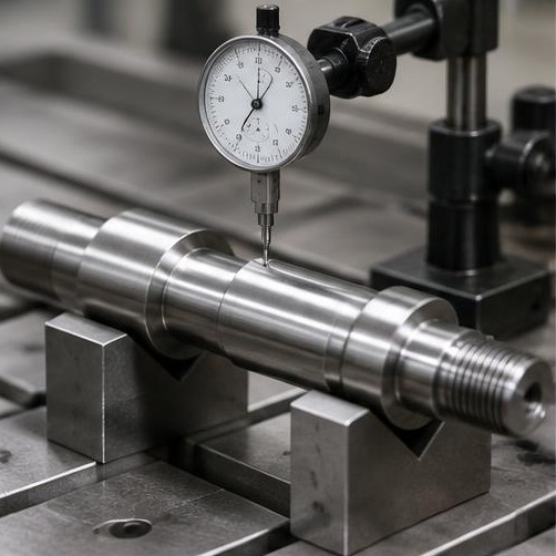
Illustrative machining and inspection imagery. - 03 / 04
Features
Dimension keyways to DIN 6885 or ANSI, specify thread class (6g), circlip grooves to DIN 471 and centre holes if the shaft will be reground.
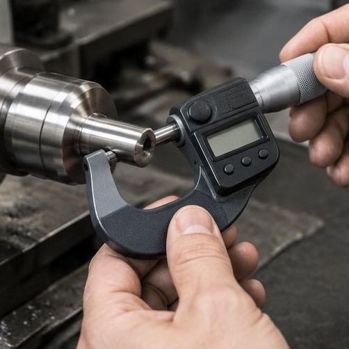
Illustrative machining and inspection imagery. - 04 / 04
Finish and protection
Give Ra values on bearing and seal surfaces (Ra 0.8 µm typical). For export, request VCI wrapping and individual tubes or crates to prevent bending in transit.
Typical callouts, feature by feature
Usual practice for shafts of this type. Replace any line with the figure your bearing, seal or coupling supplier specifies, and mark that dimension as functional.
Bearing journal
Inner ring seat
- Fit
- k6 for a rotating load, j6 where the ring must still be pressed by hand
- Geometry
- Runout to the journal datum, typically 0.02 mm TIR
- Finish
- Around Ra 0.8 µm, ground or finish-turned
- Shoulder
- Square face with a fillet smaller than the ring corner radius
- Measured with
- Outside micrometer, plus a dial test indicator between centres
Seal diameter
Radial lip seal counterface
- Fit
- h6, or the diameter band the seal maker specifies
- Finish
- About Ra 0.2–0.8 µm, free of axial machining marks
- Edges
- Lead-in chamfer or radius so the lip is not cut on assembly
- Condition
- No nicks, no burrs, no spiral turning lay under the lip
- Measured with
- Outside micrometer; finish by comparison against a roughness sample
Keyway
Parallel key seat
- Standard
- DIN 6885-1, or the ANSI equivalent, stated on the drawing
- Width class
- N9 for a normal fit, P9 for a tight fit, H9 for a free fit
- Depth
- Dimensioned from the opposite surface, not from the keyway floor
- Corners
- Radius or run-out specified so the cutter can finish the slot
- Measured with
- Vernier caliper and depth measurement; indicator for symmetry
Circlip groove
External retaining ring
- Standard
- DIN 471 groove diameter and width for the nominal shaft size
- Edges
- Sharp-edged groove walls, deburred bore mouth
- Position
- Dimensioned to the located face, with its own tolerance
- Measured with
- Vernier caliper and a groove gauge or the ring itself
Threads
Lock nuts and couplings
- Class
- 6g for external metric threads unless the mating part needs otherwise
- Relief
- Undercut or runout groove at the root of the thread
- Alignment
- Runout of the thread relative to the journals where a nut preloads a bearing
- In house
- CNC turning and auto tapping from M3 to M32
Centres and protection
Regrinding and transit
- Centre holes
- DIN 332 protected centres, retained if the shaft will be reground
- Straightness
- Called out over the free length where the shaft is slender
- Packing
- VCI anti-rust film, then an individual tube or V-block cradle
- Crate
- ISPM-15 heat-treated and stamped, marked with part number and weights
General tolerance against a named ISO 286 fit
Both appear on the same shaft drawing, and confusing them is the single most common cost error. The figures below are for a nominal Ø25 mm diameter.
| Criterion | ISO 2768-m general tolerance Everything not functional | ISO 286 fit, for example h6 Journals, seals, coupling seats |
|---|---|---|
| Tolerance band at Ø25 | ±0.2 mm, a 0.4 mm wide band | Ø25 h6 is 0 to −0.013 mm, a 13 µm band |
| Where it belongs | Free lengths, step diameters, chamfers, non-mating faces | Bearing journals, seal diameters, pulley and coupling seats |
| How it is checked | Vernier caliper, one reading | Outside micrometer, temperature-settled part, logged reading |
| Finishing operations needed | As-turned finish is normally acceptable | Finish pass with a dedicated tool, often a separate operation |
| Surface finish implied | No requirement unless stated | Ra 0.8 µm or better so the fit means something |
| Effect on piece price | Baseline | Adds setup, finishing and inspection time per feature |
| Applied to every diameter | Correct and intended | The most expensive mistake on a shaft drawing |
IT6 widens with diameter: about 13 µm at Ø25 and about 16 µm at Ø80. A mating H7 bore at Ø25 is +0.021 to 0 mm. Quote the nominal size with the fit, never the fit alone.
Shaft figures worth memorising
- 0.02 mm
- Typical runout, TIR, on a pump shaft
- 13 µm
- Width of an IT6 band at Ø25
- Ra 0.8 µm
- Usual bearing journal finish
- Ø400 × 1200 mm
- Conventional turning envelope
Referenced to the bearing journals as datum, measured with a dial test indicator.
Ø25 h6 is 0 to −0.013 mm; the mating H7 bore is +0.021 to 0 mm.
Seal counterfaces are finer, roughly Ra 0.2–0.8 µm with no axial lay.
Longer shafts and second operations are run alongside the CNC turning centres.
The short answer
What to put on a precision shaft drawing
Name the grade and its condition, apply ISO 286 fits only to the journals, seal diameters and coupling seats, and leave the rest to ISO 2768-m. Add runout referenced to the journals as datum, around 0.02 mm TIR for pump shafts. Dimension keyways to DIN 6885 with a width class, circlip grooves to DIN 471 and threads to class 6g. Give Ra values on bearing and seal surfaces only, and specify VCI wrapping with tubes or cradles for export.
- Common grades: SS 316, SS 410, EN8, EN24, with condition stated
- EN 10204 3.1 material certificate on request, asked for at RFQ stage
- Plating and heat treatment by qualified partners, re-inspected dimensionally in house
- Inspection by micrometer, bore gauge, height gauge and dial test indicator; no CMM on site
- Auto tapping M3 to M32; conventional turning to Ø400 × 1200 mm
Keep exploring
Related capabilities, materials and markets
Everything below is machined in the same Pune plant to the same ISO 9001:2015 system. Follow whichever is closest to the part you are sourcing.
Related resources
6- How to Source CNC Machined Parts from India: A Buyer's Guide
- PTFE vs PEEK vs Delrin vs Nylon: Choosing a Machinable Plastic
- Incoterms Explained for Machined Parts Buyers: EXW, FOB and CIF
- 10 Ways to Reduce the Cost of CNC Machined Parts
- Export Packaging for Machined Parts: VCI, ISPM-15 and Crating
- China+1 Sourcing for Precision Machined Components: Why India
Machining capabilities
4Request for quotation
Send your drawing. Get a quote in 24 hours.
Upload STEP, IGES or PDF files. NDA available on request. Quoting: Precision Shaft Design Checklist for Pump, Motor and Gearbox Shafts.